Betaflight Connector Standard
Version Change Register
| Version # | Revision Date | Changes, Reasons, and Notes |
|---|---|---|
| Draft 0.1 | 27 April 2023 | Initial Draft Format |
| Draft 0.2 | 08 May 2023 | Added Logo and pinout correction |
| Draft 0.3 | 16 June 2024 | Adjustment to GPS to 4 pin, moved to RX and renamed, and adding SWD |
| Version 1.0 | 14 April 2025 | Formalize standard |
| Version 1.1 | 24 April 2025 | Add option for 10P ESC socket |
| Version 1.2 | 08 May 2025 | Add reference schematic + board renders |
| Version 1.3 | 16 December 2025 | Add reference schematic + board renders for 4-pin and 3-pin camera connectors |
| Version 2.0 | 03 August 2026 | Remove the 6-pin UART+I2C (GPS) connector; GPS now uses the 4-pin serial connector. The 6-pin option is deprecated due to the risk of a GPS being plugged into the physically identical 6-pin digital VTX connector, whose 8-26V supply will damage or destroy the GPS |
| Version 2.1 | 13 August 2026 | Add optional 2-pin I2C connector for devices that already take power from another connector, such as a GPS with an onboard compass. The 4-pin I2C connector remains the recommended and preferred option. Specify the ext. power connector as JST PH, so that a power connector can no longer be mated with a signal harness |
| Version 2.2 | 31 August 2026 | Add the 4-pin FDCAN connector, adopting the JST GH CAN connector of the PX4 and ArduPilot connector standard unchanged so that existing CAN peripherals and harnesses work without adapters |
Introduction
Drone usage has grown rapidly in recent years, along with a thriving community and a wide variety of drone types now available on the market. Many manufacturers produce drones and components, but the lack of standardization has led to compatibility issues between parts.
This fragmentation has made it challenging for users to build and maintain multi-rotor drones. As the industry continues to expand, the need for standardized components has become increasingly clear.
To address this, we have established a standard for drone connectors designed to ensure compatibility across components from different manufacturers. This standard will reduce confusion, streamline the building and maintenance process, and contribute to a more efficient and cost-effective drone industry.
Connector Standards
Availability
Any harness should be widely available and easy to obtain. The harness should be available from multiple sources and should be easy to obtain from any source.
Using yellow connectors is preferred to make it clear the new standard is used. Provide legacy wire harness in addition to the standard for current products.
JST SH Series as Standard for Connectors.
JST-SH is a widely used and reliable connector that has proven to be a robust choice for drone applications. The connector should be the standard for all drone manufacturers, ensuring compatibility between components from different manufacturers.
Two connections do not use JST SH, for different reasons. Power-only connections use JST PH so that they cannot be mated with a signal harness, see Ext. Power Pin Configuration. FDCAN uses JST GH because it adopts the PX4 and ArduPilot CAN standard in full, see FDCAN Pin Configuration.
JST GH Series as Optional Component.
Some manufacturers also use other firmware, such as Ardupilot or Pixhawk, which have their own standard. This connector type is optional for drone manufacturers, allowing them to choose the connector type that best suits their needs as long as they provide a harness for both platforms.
Where an established standard already covers a connection well, this standard adopts it as it is rather than defining a competing pinout. FDCAN is taken wholesale from the PX4 and ArduPilot connector standard, JST GH included, so that the existing ecosystem of CAN peripherals and harnesses works without adapters. Adopting an outside standard this way is deliberate practice rather than an exception to be minimised, since a second, incompatible CAN pinout would fragment exactly what this document exists to unify. JST GH is therefore not optional for FDCAN, even on a board that is otherwise entirely JST SH.
ESC Pin Configuration
We recommend using twisted wires to eliminate any confusion about the mirroring of the connector and to ensure that the same wiring order is used on both sides of the connection.
V+ connection from the ESC to FC will typically carry VBAT voltage direct from the battery connection. The ESC V+ connection is an Input Voltage to the FC whilst RX, GPS and other connectors' V+ pads carry output from the FC's onboard voltage regulators.
In some cases VTX or camera connectors may offer VBAT voltage directly but due to voltage fluctuations induced by the motors the use of VBAT direct to VTXs or cameras is discouraged. To minimise the risk to sensitive VTX hardware it is advisable to provide an additional high voltage regulator for such components. Recommended continuous power draw for this high voltage VTX regulator is ~18W, translating to at least a 9V/2A part, and output voltage should be between 8-12V, preferably 10V.
Standard ESC Pin Configuration
The pin configuration for the JST SH connector is as follows:
| Pin # | Signal Name | Description |
|---|---|---|
| 1 | V+ (VBAT) | Power |
| 2 | GND | Ground |
| 3 | Current | Current |
| 4 | Telemetry | Telemetry |
| 5 | Signal 1 | Motor 1 |
| 6 | Signal 2 | Motor 2 |
| 7 | Signal 3 | Motor 3 |
| 8 | Signal 4 | Motor 4 |
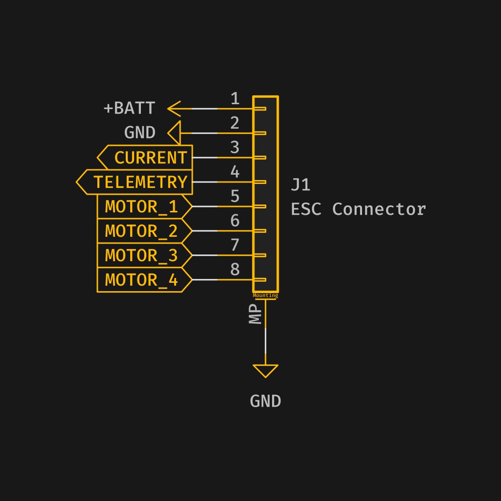
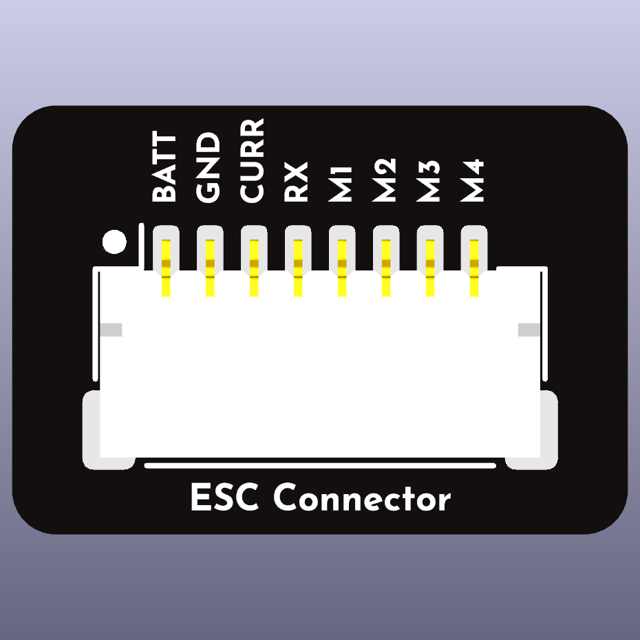
ESC with additional power requirements
An additional 2-pin connector for power (ext. power) can be used for high-powered devices or if the user wants to use an external power source. See Ext. Power Pin Configuration for that connector.
Alternative a 10-pin connector can be used:
| Pin # | Signal Name | Description |
|---|---|---|
| 1 | V+ (VBAT) | Power |
| 2 | V+ (VBAT) | Power |
| 3 | GND | Ground |
| 4 | GND | Ground |
| 5 | Current | Current |
| 6 | Telemetry | Telemetry |
| 7 | Signal 1 | Motor 1 |
| 8 | Signal 2 | Motor 2 |
| 9 | Signal 3 | Motor 3 |
| 10 | Signal 4 | Motor 4 |
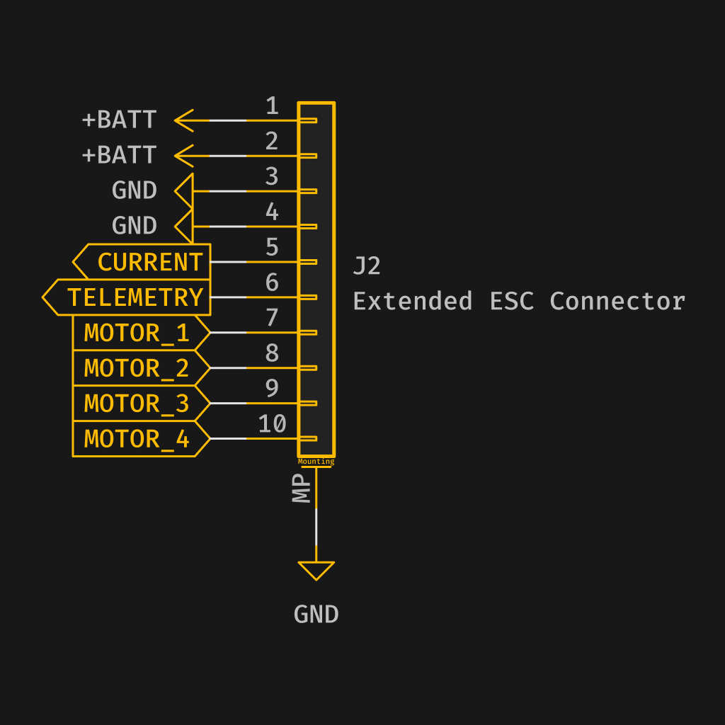
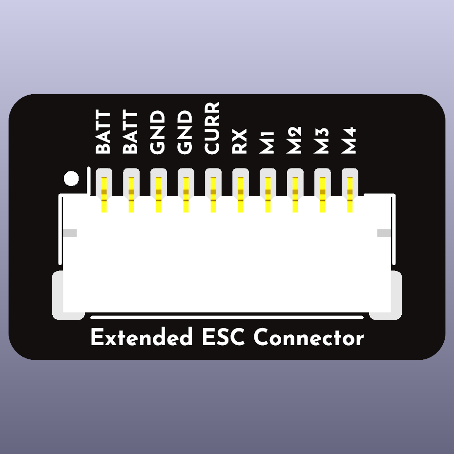
Ext. Power Pin Configuration
Power-only connections use the JST PH series (2.0 mm pitch), not JST SH. This deliberate departure from the JST SH standard exists so that a connector carrying VBAT cannot physically be mated with any signal harness in this standard.
The pin configuration for the 2-pin JST PH connector is as follows:
| Pin # | Signal Name | Description |
|---|---|---|
| 1 | V+ (VBAT) | Power |
| 2 | GND | Ground |
Red wire for V+ and black wire for GND, as is conventional for power leads.
JST PH is rated at approximately 2A per contact. Where the load exceeds that, use direct solder pads or an XT30 rather than stretching this connector beyond its rating.
A 2-pin power connection must never be presented on a JST SH or JST GH socket, even on legacy designs. Both are used for signal elsewhere in this standard, and a power socket that accepts a signal harness will destroy whatever is plugged into it by mistake.
Serial (UART) Pin Configuration (RX, GPS, and other 5V serial devices)
The pin configuration for the 4 pin JST SH connector is as follows:
| Pin # | Signal Name | Description |
|---|---|---|
| 1 | V+ (5V) | Power |
| 2 | GND | Ground |
| 3 | Signal 1 | RX |
| 4 | Signal 2 | TX |
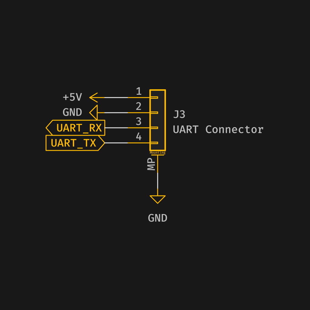
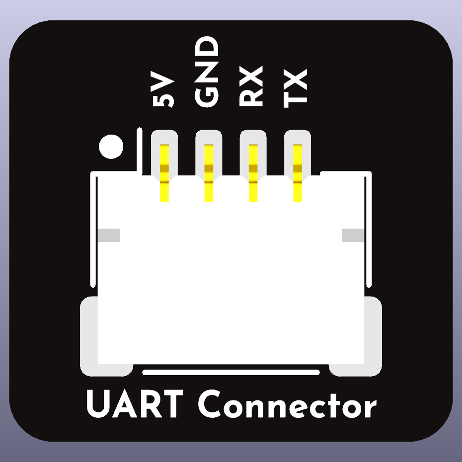
This connector could also be used for any number of serial devices.
Where a GPS module uses a 6-pin cable, e.g. a combined GPS and magnetometer that requires I2C, use a Y cable that splits across a 4-pin serial connector and a separate I2C connector. The GPS takes its 5V and ground from the serial connector, so the I2C leg carries data and clock only and may terminate in either the 4-pin I2C connector (preferred) or the 2-pin I2C connector. Note that mounting the magnetometer and GPS together is not recommended.
The 6-pin UART+I2C connector has been removed from the standard and must no longer be used for GPS or any other device. GPS modules use the 4-pin serial connector above.
The 6-pin serial footprint is physically identical to the 6-pin digital VTX connector, whose pin 1 carries 8-26V. A GPS fitted with a 6-pin cable can be plugged into the digital VTX connector by mistake, applying VTX voltage to the GPS 5V rail and damaging or destroying the GPS. For this reason the 6-pin option is deprecated and should not appear on new designs.
I2C Pin Configuration
4-pin I2C Connector (Preferred)
The pin configuration for the 4-pin JST SH connector is as follows:
| Pin # | Signal Name | Description |
|---|---|---|
| 1 | V+ (5V) | Power |
| 2 | GND | Ground |
| 3 | Signal 1 | SDA |
| 4 | Signal 2 | SCL |
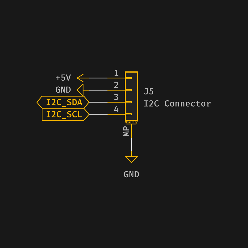
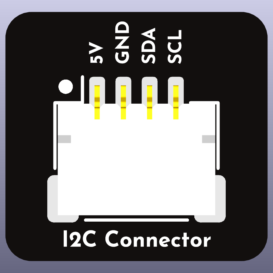
The I2C connector should be used for all I2C devices, including compasses (magnetometers), barometers, and other sensors.
On STM devices pins are shared with PB10 and PB11 for TX3 and RX3 so please keep this in mind when using onboard I2C device such as compasses and barometers.
2-pin I2C Connector (Optional)
The pin configuration for the 2-pin JST SH connector is as follows:
| Pin # | Signal Name | Description |
|---|---|---|
| 1 | Signal 1 | SDA |
| 2 | Signal 2 | SCL |
This connector carries data and clock only, for devices that already take their 5V and ground from another connector. The intended use is a GPS with an onboard compass: the module is powered through its 4-pin serial connector, so a second power and ground pair on the I2C leg of the harness is redundant.
The 4-pin I2C connector above remains the recommended and preferred option, and should be provided wherever board space allows. A board may fit both, sharing the same bus. Any device that has no other source of power must use the 4-pin connector.
The 2-pin ext. power connector is JST PH specifically so that it cannot accept this harness, since applying VBAT to SDA and SCL will destroy the connected device.
Legacy boards predating v2.1 may still present a 2-pin power connection on a JST SH socket. Do not fit a 2-pin I2C connector on such a board, and do not use a 2-pin JST SH socket for power on new designs.
FDCAN Pin Configuration
FDCAN adopts the CAN connector of the PX4 and ArduPilot connector standard unchanged: a 4-pin JST GH (1.25 mm pitch) connector with the pinout below. Nothing here is redefined by Betaflight. The reason for adopting rather than redefining is that CAN peripherals, splitters and harnesses in this form are already widely available, and a competing Betaflight CAN pinout would only fragment that supply.
The pin configuration for the 4-pin JST GH connector is as follows:
| Pin # | Signal Name | Description |
|---|---|---|
| 1 | V+ (5V) | Power |
| 2 | Signal 1 | CAN_H |
| 3 | Signal 2 | CAN_L |
| 4 | GND | Ground |
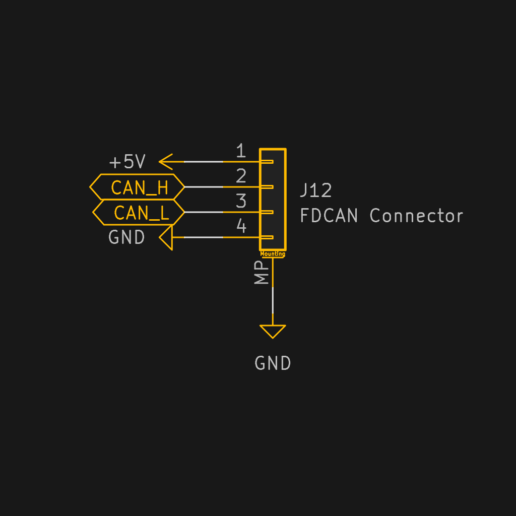
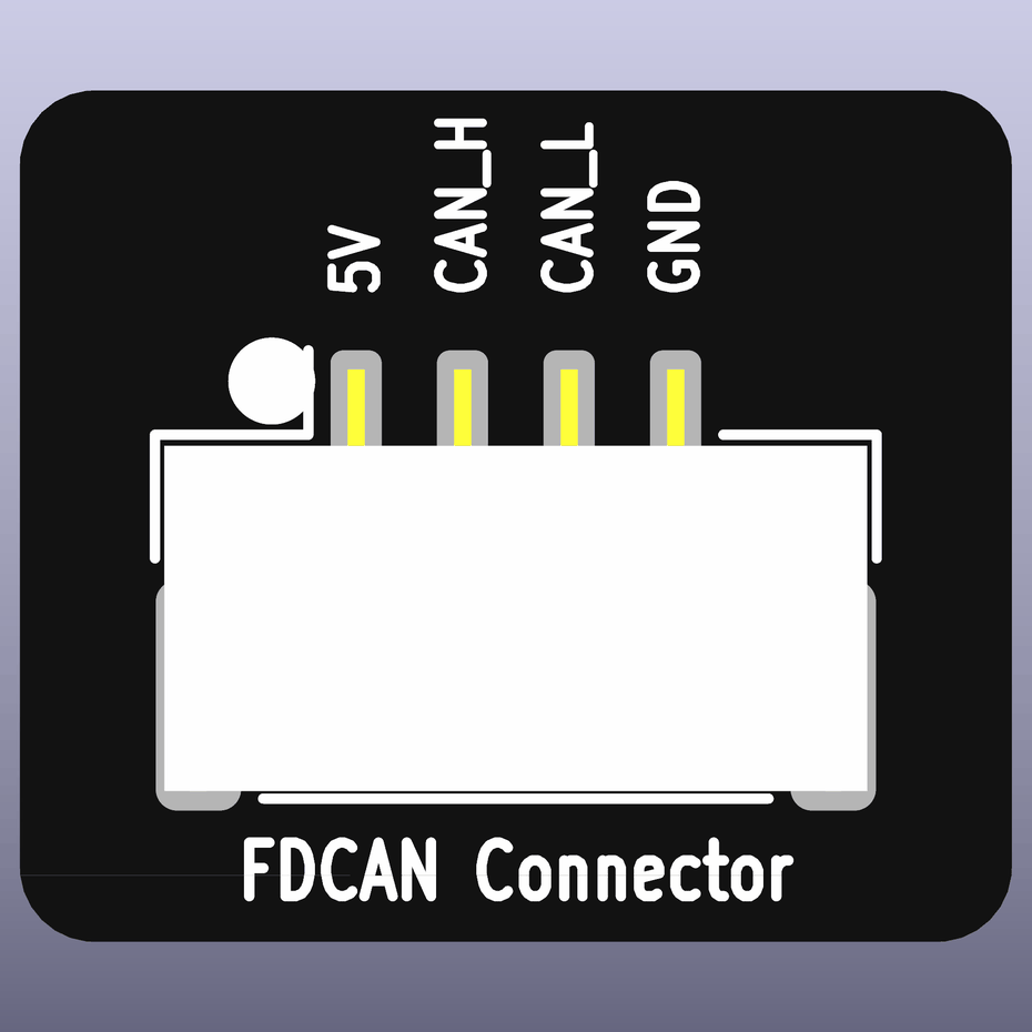
The pin order differs from every other connector in this standard: ground is on pin 4, not pin 2. This follows from adopting the PX4 and ArduPilot pinout as-is, and must not be "corrected" to match the rest of this document, as that would break compatibility with every existing CAN peripheral. The 1.25 mm GH pitch means the connector cannot be mated with a 4-pin JST SH serial or I2C harness.
CAN is a bus, not a point-to-point link. Boards intended to sit in the middle of a bus should provide two CAN connectors wired in parallel so peripherals can be daisy-chained, and the two physical ends of the bus require 120 Ω termination. Where a board provides on-board termination it should be selectable, so that a board fitted mid-bus does not add a third terminator.
The 5V supply on pin 1 comes from the FC's onboard regulator and is intended for peripherals such as CAN GPS, compass, or ESC telemetry nodes. Higher-powered nodes should take their power from the ext. power connector or directly from the battery.
Analog Camera Pin Configuration
It is no longer recommended to have an analogue OSD chip on the FC. The recommendation is to emulate the digital standard, and place the OSD chip on the VTX.
This would render these connectors redundant.
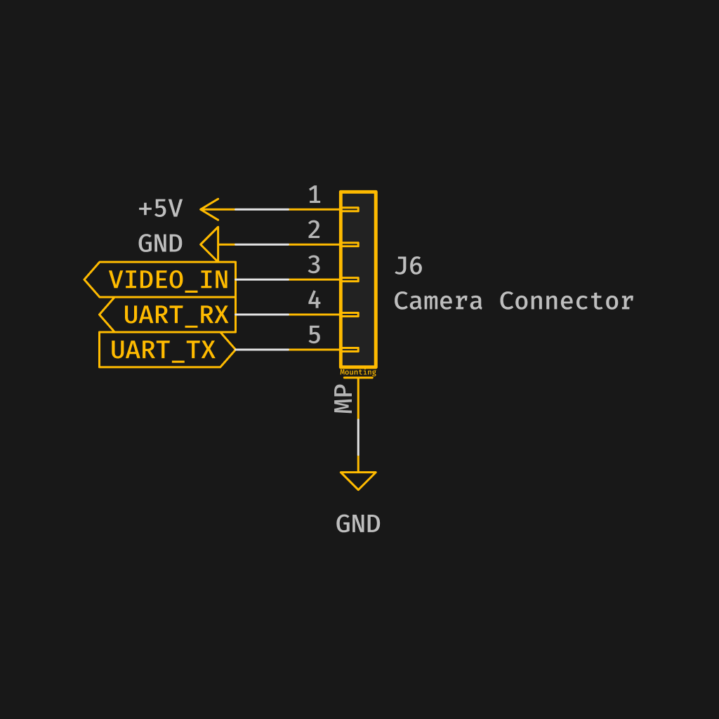
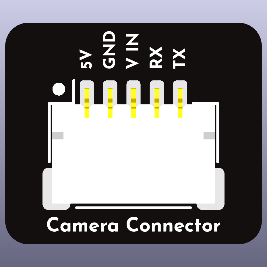
5-pin Connector
The pin configuration for the 5-pin JST SH connector is as follows:
| Pin # | Signal Name | Description |
|---|---|---|
| 1 | V+ (5v) | Power |
| 2 | GND | Ground |
| 3 | Signal 1 | Video |
| 4 | Signal 2 | RX |
| 5 | Signal 3 | TX |
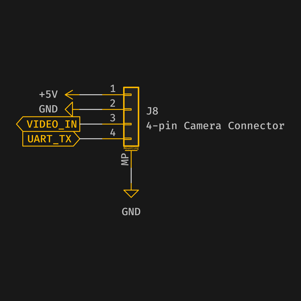
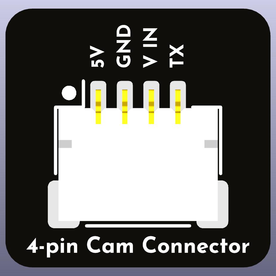
4-pin Connector
The pin configuration for the 4-pin JST SH connector is as follows:
| Pin # | Signal Name | Description |
|---|---|---|
| 1 | V+ (5v) | Power |
| 2 | GND | Ground |
| 3 | Signal 1 | Video |
| 4 | Signal 2 | TX |
3-pin Connector
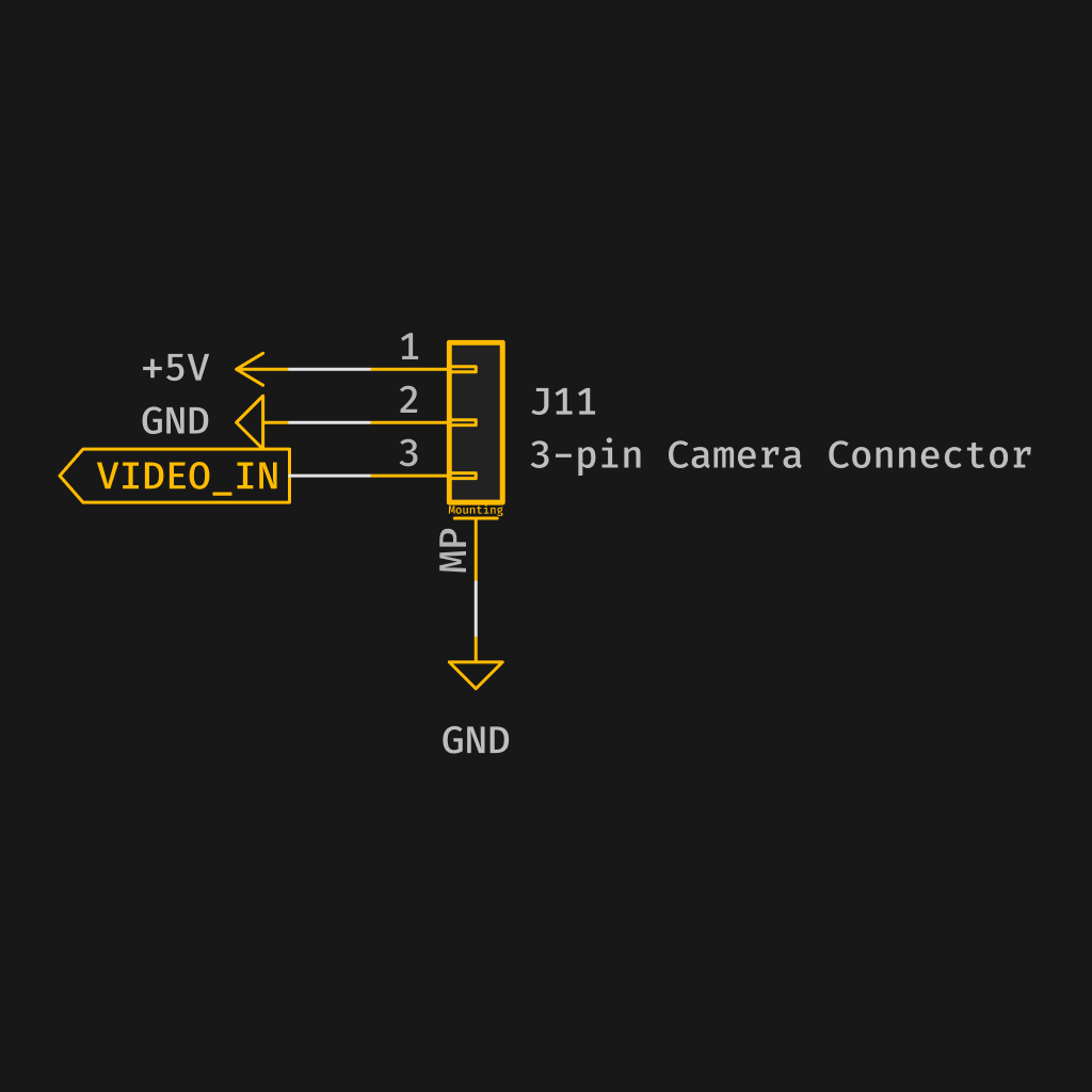
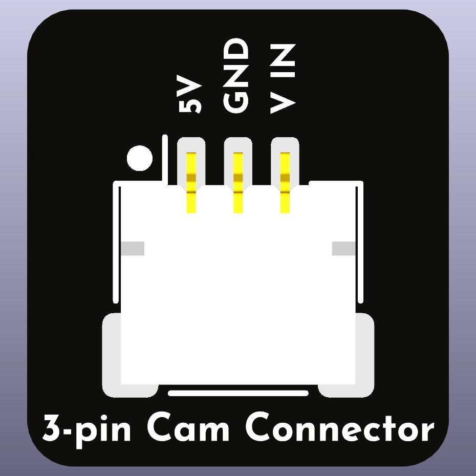
The pin configuration for the 3-pin JST SH connector is as follows:
| Pin # | Signal Name | Description |
|---|---|---|
| 1 | V+ (5v) | Power |
| 2 | GND | Ground |
| 3 | Signal 1 | Video |
VTX Pin Configuration
The pin configuration for the JST SH connector is as follows:
| Pin # | Signal Name | Description |
|---|---|---|
| 1 | V+ (8-12V) | Power |
| 2 | GND | Ground |
| 3 | Signal 1 | Video |
| 4 | Signal 2 | RX |
| 5 | Signal 3 | TX |
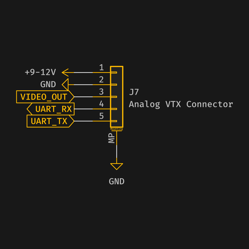
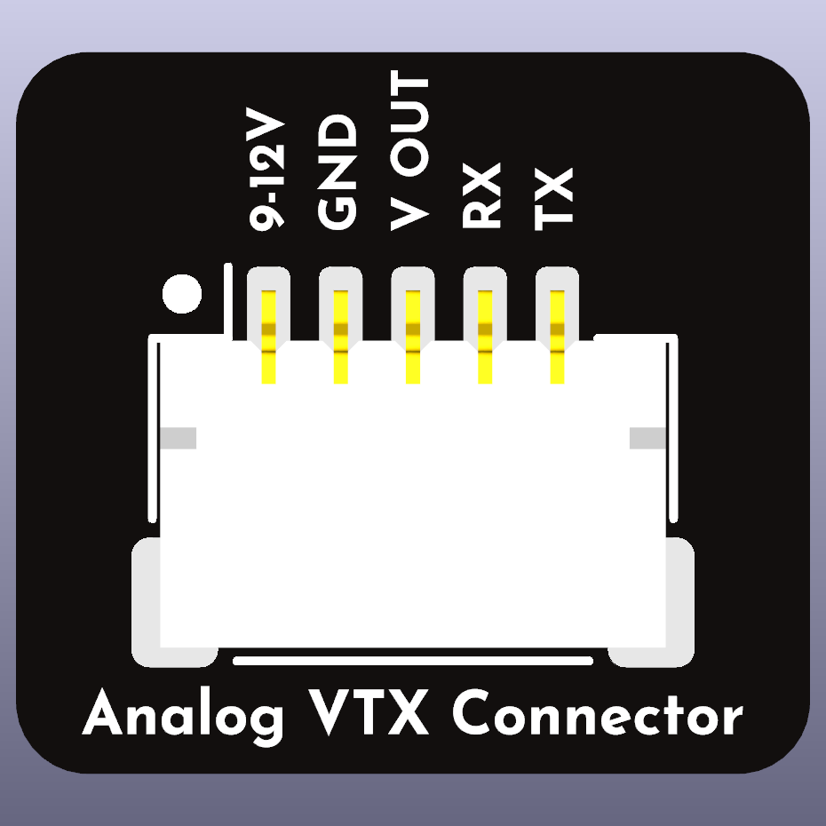
10V regulated for V+ is preferred for providing analogue VTX power.
Digital Video Transmitter Pin Configuration
The current pin configuration for the JST SH connector is as follows:
| Pin # | Signal Name | Description |
|---|---|---|
| 1 | V+ (8-26V) | Power |
| 2 | GND | Ground |
| 3 | Signal 1 | TX |
| 4 | Signal 2 | RX |
| 5 | GND | Ground (DJI) |
| 6 | Signal 3 | SBUS (DJI) |
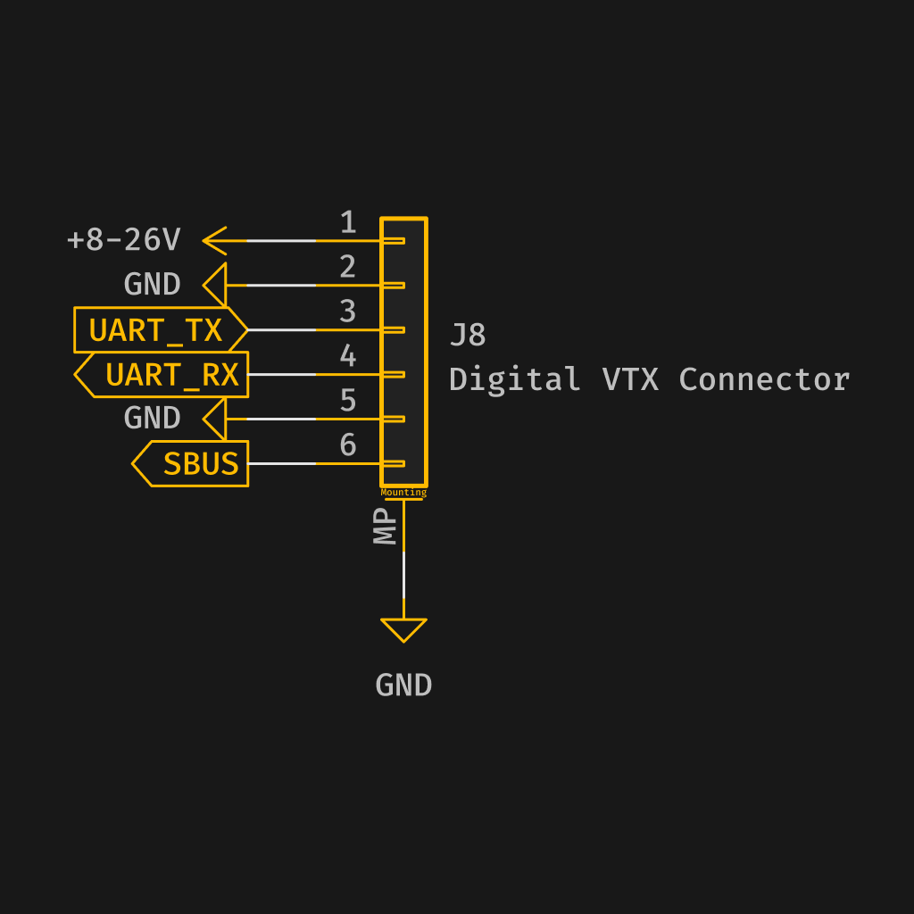
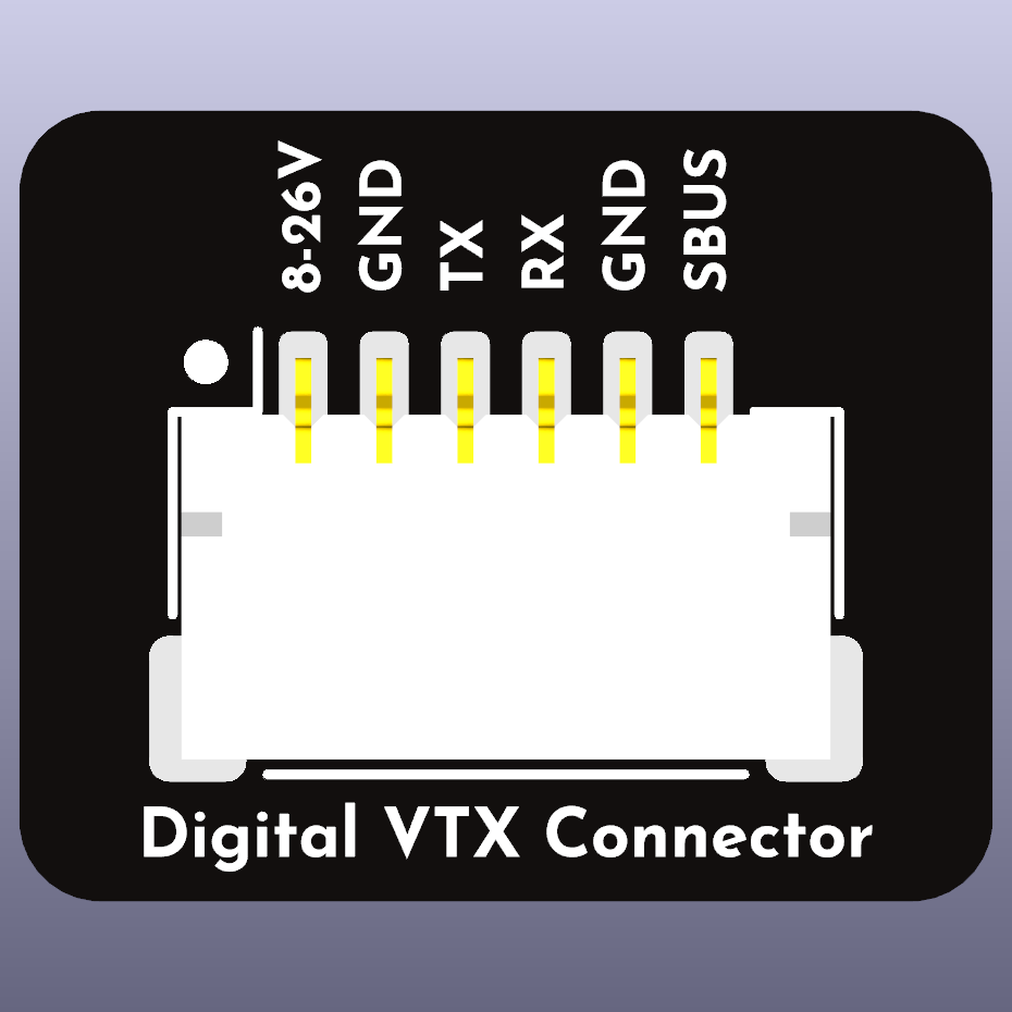
10V for V+ is preferred for digital video transmitter power.
SWD Pin Configuration
The pin configuration for the JST SH connector is as follows:
| Pin # | Signal Name | Description |
|---|---|---|
| 1 | V+ (3V3) | Power |
| 2 | GND | Ground |
| 3 | Signal 1 | SWDIO |
| 4 | Signal 2 | SWCLK |
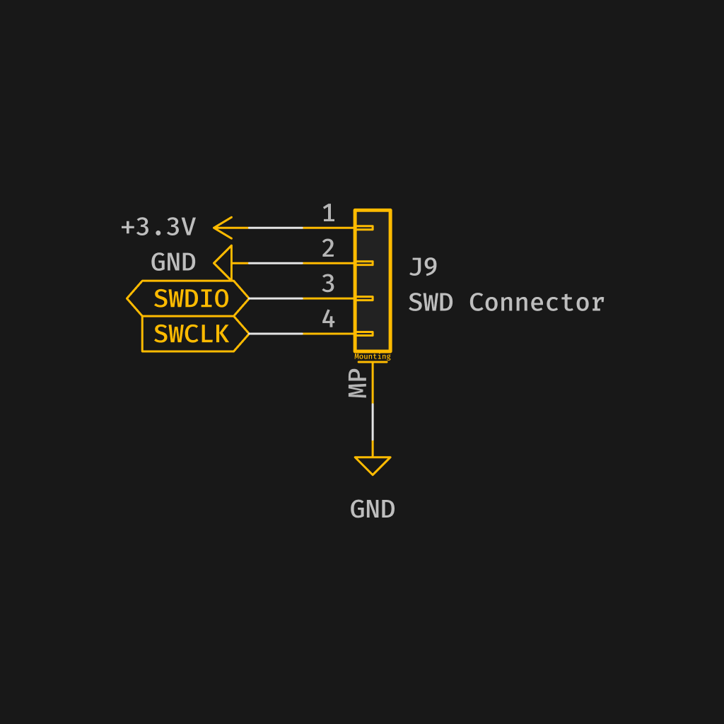
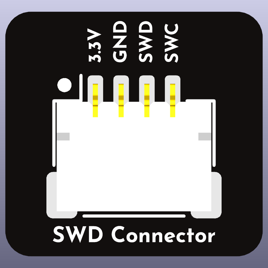
This connector is recommended to be placed for prototyping boards when supplying to the Betaflight team for debugging and testing.
Logo
The provided logo should be used to identify the connector as a Betaflight standardized connector. The logo should be used on all components that use the standardized connector system and can be used on PCBs, packaging, and other marketing materials. This way users know that the component is compatible with other components that use the standardized connector system.
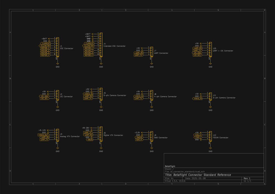
Complete Schematic
SVG
PDF
KiCad Schematic
Betaflight App
The Betaflight App firmware flasher tab provides a link to each board in our documentation. This link will take users to the documentation for the board they have selected.
Each boards documentation section should include a list of components that are compatible with the standardized connector system. Documentation should include schematics, pinouts, and other information that will help users build and maintain their drones.
Conclusion
The standardized connector system described in this document will help reduce confusion and ensure compatibility between components from different manufacturers, making it easier for users to build and maintain multi-rotor drones. We strongly recommend that drone manufacturers and component manufacturers adopt the Betaflight Connector Standard to benefit the entire drone community.